
Understanding the fundamental differences between DC MCB and AC circuit breakers is crucial for electrical professionals and engineers working with modern power systems. While both devices serve the essential function of protecting electrical circuits from overcurrent conditions, their internal mechanisms, design considerations, and operational characteristics differ significantly due to the distinct nature of direct current versus alternating current applications.
The growing adoption of renewable energy systems, electric vehicles, and DC-powered industrial equipment has made dc mcb technology increasingly important in contemporary electrical installations. These specialized circuit protection devices operate under different physical principles compared to their AC counterparts, requiring specific design adaptations to handle the unique challenges presented by direct current flow, including arc extinction difficulties and continuous current characteristics.
Arc Extinction Mechanisms and Current Interruption
Arc Formation Differences in DC vs AC Systems
The most significant difference between dc mcb and AC circuit breakers lies in their arc extinction mechanisms. In AC systems, the current naturally crosses zero twice per cycle, providing regular opportunities for arc extinction as the alternating current momentarily drops to zero amplitude. This zero-crossing characteristic makes it relatively easier for AC circuit breakers to interrupt fault currents.
Direct current systems present a fundamentally different challenge for dc mcb devices. Since DC maintains a constant current flow without natural zero-crossing points, the arc formed during circuit interruption remains sustained and more difficult to extinguish. The continuous nature of direct current means that once an arc establishes between the contacts during breaking, it tends to maintain itself due to the steady energy supply.
This persistent arc characteristic in DC applications requires dc mcb units to employ more sophisticated arc extinction techniques. These may include enhanced magnetic blowout systems, specialized contact materials, and improved arc chute designs to forcibly extinguish the arc without relying on natural current zero points.
Magnetic Blowout Systems and Arc Control
DC MCB devices typically incorporate stronger magnetic blowout systems compared to AC circuit breakers. These systems use magnetic fields to rapidly stretch and cool the arc, forcing it into arc chutes where it can be safely extinguished. The magnetic field effectively pushes the arc away from the main contacts, preventing re-ignition and ensuring complete current interruption.
The design of arc chutes in dc mcb applications also differs significantly from AC versions. DC arc chutes typically feature more plates or segments to divide the arc into smaller, more manageable portions. Each segment experiences lower voltage, making it easier to achieve complete arc extinction across the entire breaking distance.
Advanced dc mcb designs may incorporate additional features such as permanent magnets or electromagnetic coils to enhance the magnetic blowout effect. These components work together to create a strong, directed magnetic field that rapidly moves the arc into the extinction chamber, ensuring reliable operation even under high-current DC fault conditions.
Voltage Ratings and System Compatibility
Voltage Handling Characteristics
The voltage ratings for dc mcb units require different considerations compared to AC circuit breakers due to the nature of direct current voltage characteristics. DC systems maintain constant voltage levels without the peak-to-RMS relationships found in AC systems, which affects how circuit breakers must be rated and designed for safe operation.
DC MCB devices often require higher voltage ratings for equivalent breaking capacity compared to AC circuit breakers. This is because the absence of natural current zeros in DC systems means the full system voltage remains present across the breaking contacts throughout the interruption process. AC circuit breakers benefit from the sinusoidal voltage characteristic that provides lower instantaneous voltages during certain portions of the cycle.
Modern dc mcb products are specifically engineered to handle the continuous voltage stress associated with direct current applications. These devices undergo rigorous testing to ensure they can safely interrupt DC circuits at their rated voltages without flashover or re-ignition occurring between the open contacts.
System Integration and Application Requirements
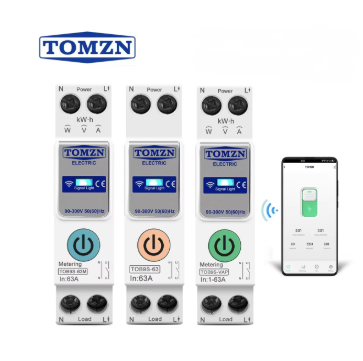
The integration of dc mcb devices into electrical systems requires careful consideration of the specific DC application requirements. Solar photovoltaic systems, battery storage installations, and DC motor drives each present unique operational characteristics that influence circuit breaker selection and installation requirements.
DC MCB units must be compatible with the grounding schemes commonly used in DC systems, which may differ from traditional AC grounding methods. Some DC systems operate with positive grounding, negative grounding, or isolated configurations, each requiring specific considerations for proper circuit breaker coordination and protection scheme design.
The coordination between multiple dc mcb devices in series or parallel configurations also requires specialized analysis. Unlike AC systems where standard coordination curves apply, DC protection coordination must account for the unique time-current characteristics of DC fault conditions and the specific response of dc mcb devices to these conditions.
Current Carrying Capacity and Thermal Management
Steady-State Current Handling
The current carrying capacity of dc mcb devices reflects the continuous nature of direct current flow. Unlike AC systems where the current varies sinusoidally and provides brief periods of reduced thermal stress, DC systems maintain constant current levels that create continuous heating effects in circuit breaker components.
This constant current characteristic requires dc mcb designs to incorporate enhanced thermal management features. The contact materials, conductor cross-sections, and heat dissipation mechanisms must be optimized to handle the sustained thermal loading without degradation over the expected service life of the device.
The thermal rating considerations for dc mcb applications often involve derating factors when operating in high-temperature environments or when multiple units are installed in close proximity. The continuous nature of DC current means there are no natural cooling periods, making thermal management a critical design consideration.
Contact Materials and Erosion Characteristics
Contact materials in dc mcb devices must withstand different erosion patterns compared to AC circuit breakers. The absence of current zeros in DC systems means that any contact erosion occurs continuously during arcing events, rather than being distributed across multiple zero-crossings as in AC applications.
DC MCB manufacturers typically use specialized contact alloys designed to resist the unique erosion patterns associated with DC arcing. These materials may include silver-based alloys with specific additives to improve arc resistance and reduce contact welding tendencies under DC fault conditions.
The contact geometry and spring mechanisms in dc mcb designs also require optimization for DC applications. The contact pressure and wiping action must be sufficient to break through any oxidation or surface films that may develop during normal DC operation, ensuring reliable circuit interruption when required.
Breaking Capacity and Fault Current Interruption
Short Circuit Current Characteristics
The breaking capacity ratings of dc mcb devices reflect the challenges associated with interrupting DC fault currents. DC fault currents can reach high magnitudes quickly and maintain those levels without the natural current limitation provided by AC system impedance characteristics.
In DC systems, particularly those with large capacitor banks or battery storage, fault currents can exhibit different time characteristics compared to AC faults. The initial rate of current rise may be extremely rapid, followed by a sustained high-current condition that challenges the interrupting capability of the dc mcb device.
DC MCB units must be tested and rated for their ability to interrupt these specific DC fault current characteristics. The testing standards for dc mcb devices include requirements for interrupting fault currents with rapid rise times and sustained high-magnitude conditions that differ from standard AC circuit breaker testing protocols.
Recovery Voltage and Re-ignition Prevention
The recovery voltage characteristics following current interruption differ significantly between dc mcb and AC circuit breakers. In AC systems, the recovery voltage builds gradually following current interruption, providing time for the contact gap to develop sufficient dielectric strength to withstand the system voltage.
DC systems present the full system voltage across the circuit breaker contacts immediately upon current interruption. This immediate voltage application, combined with the continuous nature of the voltage, requires dc mcb designs to achieve rapid contact separation and arc extinction to prevent re-ignition of the arc across the contact gap.
The dielectric recovery characteristics of dc mcb devices must be optimized for the specific requirements of DC applications. This includes consideration of the contact gap distance, insulation materials, and arc chute design to ensure adequate dielectric strength is maintained under all operating conditions.
Application-Specific Design Considerations
Environmental and Installation Factors
DC MCB applications often involve unique environmental conditions that influence device design and selection. Solar photovoltaic installations expose circuit breakers to outdoor conditions, temperature extremes, and UV radiation that require specific material selections and enclosure ratings.
The mounting and installation requirements for dc mcb devices may differ from AC circuit breakers due to the specific needs of DC system configurations. Battery systems, for example, may require circuit breakers with specific terminal arrangements or mounting orientations to accommodate the layout constraints of battery enclosures.
Vibration resistance and mechanical durability requirements for dc mcb applications can be more stringent than AC applications, particularly in mobile or transportation applications where DC systems are commonly used. The circuit breaker design must maintain reliable operation despite mechanical stresses that may not be present in stationary AC installations.
Maintenance and Service Considerations
The maintenance requirements for dc mcb devices reflect the unique operational stresses associated with DC applications. Contact inspection intervals, arc chute maintenance, and calibration procedures must account for the specific wear patterns and aging characteristics associated with DC operation.
Service life expectations for dc mcb components may differ from AC circuit breakers due to the continuous nature of DC operation and the absence of current zeros that provide brief periods of reduced stress. Predictive maintenance programs for DC systems must consider these factors when establishing inspection and replacement schedules.
The diagnostic capabilities built into modern dc mcb devices may include features specifically designed to monitor the health of components under DC operational stresses. These monitoring systems can provide early warning of potential failures and optimize maintenance scheduling for maximum system reliability.
FAQ
What is the main technical difference between DC MCB and AC circuit breakers?
The primary technical difference lies in arc extinction mechanisms. DC MCB devices must forcibly extinguish arcs without natural current zero-crossings, requiring enhanced magnetic blowout systems and specialized arc chutes. AC circuit breakers benefit from natural current zeros that occur twice per cycle, making arc extinction easier.
Can an AC circuit breaker be used in a DC application?
No, AC circuit breakers should not be used in DC applications. They lack the specialized arc extinction mechanisms required for DC current interruption and may fail to safely break DC circuits, potentially leading to sustained arcing, equipment damage, or safety hazards.
Why do DC MCB devices require higher voltage ratings than equivalent AC breakers?
DC MCB devices require higher voltage ratings because they must withstand the full system voltage continuously across their contacts during and after current interruption. AC systems have varying instantaneous voltages due to their sinusoidal nature, while DC maintains constant voltage levels that create greater dielectric stress on the circuit breaker.
What applications commonly require DC MCB protection?
Common applications include solar photovoltaic systems, battery energy storage systems, electric vehicle charging infrastructure, DC motor drives, telecommunications power systems, and marine electrical systems. These applications require specialized DC circuit protection due to their unique operational characteristics and safety requirements.