
Outdoor solar installations face a unique and persistent threat that many system designers underestimate until it is too late: transient voltage surges. Whether triggered by nearby lightning strikes, grid switching events, or inductive load disturbances, these surges can travel through DC wiring and destroy inverters, charge controllers, and monitoring equipment within milliseconds. A properly selected and installed dc spd — surge protective device — is the most direct and cost-effective answer to this vulnerability, acting as the first line of defense between your solar array and the sensitive electronics downstream.
Understanding how a dc spd improves outdoor solar system protection requires looking beyond the device itself and examining the full electrical environment of a photovoltaic installation. Solar arrays are typically mounted in open, elevated, and exposed locations — exactly the conditions that maximize surge exposure. The DC side of the system, running from the panels to the inverter, carries high-voltage direct current that has no natural zero-crossing point, making surge suppression fundamentally different from AC protection. This is why purpose-built dc spd technology matters so much in solar applications, and why selecting the right device for the right voltage and energy class is a decision that directly affects system longevity and reliability.
The Surge Threat Landscape for Outdoor Solar Systems
Why Solar Installations Are Especially Vulnerable
Solar panels are installed outdoors, often on rooftops or open ground-mount structures, with long cable runs connecting strings of panels to combiner boxes and inverters. These cable runs act as antennas, capturing induced energy from nearby lightning events even when a direct strike does not occur. A lightning strike within several hundred meters of an installation can induce transient voltages of several thousand volts on unprotected DC conductors, far exceeding the withstand rating of most inverter input stages.
Beyond lightning, solar systems are also exposed to switching surges generated when large loads connect or disconnect from the grid, and to surges that propagate from the AC grid back through the inverter into the DC circuit. Each of these events represents a potential failure mode that a well-specified dc spd is designed to intercept and dissipate before the energy reaches critical components.
The financial stakes are significant. A single inverter failure caused by an unprotected surge event can cost thousands of dollars in equipment replacement, lost energy production, and labor for diagnosis and repair. When the installation is in a remote or difficult-to-access location, those costs multiply quickly. Investing in a quality dc spd at the design stage is a straightforward way to reduce this risk profile substantially.
How DC Surges Differ from AC Surges
One of the most important distinctions in surge protection engineering is the difference between AC and DC circuit behavior during a transient event. In an AC circuit, the voltage naturally crosses zero 50 or 60 times per second, which helps extinguish any arc that forms when a surge protective device clamps a transient. In a DC circuit, there is no zero crossing, meaning that once an arc forms, it tends to sustain itself and can cause the protective device to fail catastrophically if it is not specifically designed for DC operation.
This is why using an AC-rated surge protector on the DC side of a solar system is not only ineffective but potentially dangerous. A dc spd is engineered with arc-quenching geometry, appropriate varistor materials, and thermal disconnect mechanisms that account for the continuous DC voltage present in the circuit. The voltage rating of the device must also match or exceed the maximum open-circuit voltage of the solar string under worst-case temperature conditions, which in a 1000V system can approach the full rated maximum.
Selecting a dc spd with the correct maximum continuous operating voltage, or MCOV, is therefore not a minor specification detail — it is a fundamental safety and performance requirement. Undersized devices will degrade rapidly under normal operating conditions and may fail before they ever encounter a real surge event.
How a DC SPD Works Within a Solar Protection Strategy
The Clamping and Dissipation Mechanism
A dc spd operates by presenting a very high impedance to normal operating voltage while switching to a very low impedance state the moment a transient voltage exceeds its protection level threshold. This clamping action diverts the surge current away from the protected equipment and routes it safely to the grounding system, where the energy is dissipated harmlessly into the earth. The entire process happens in nanoseconds, far faster than any circuit breaker or fuse could respond.
Metal oxide varistors, commonly called MOVs, are the most widely used clamping element in dc spd devices for solar applications. MOVs offer a good balance of energy absorption capacity, response speed, and cost-effectiveness. However, MOVs do degrade with each surge event they absorb, which is why quality dc spd products include a visual status indicator — typically a window that changes color — to signal when the device has reached the end of its service life and needs replacement.
Some advanced dc spd designs combine MOV technology with gas discharge tubes or transient voltage suppression diodes to create a multi-stage protection architecture. This layered approach provides both coarse energy absorption for large events and fine clamping for smaller, more frequent transients, offering more comprehensive protection across a wider range of surge scenarios.
Placement Strategy for Maximum Effectiveness
The physical placement of a dc spd within the solar system architecture has a direct impact on how effectively it protects downstream equipment. The general principle is to install the device as close as possible to the equipment being protected, with the shortest possible lead lengths between the device terminals and the circuit conductors. Long lead lengths add inductance that reduces the effectiveness of the clamping action during fast-rise-time transients.
In a typical residential or commercial solar installation, dc spd devices are installed at the DC input of the inverter and, in larger systems, also at the output of the string combiner box. This two-point approach provides zone protection: the combiner box dc spd handles surges entering from the array side, while the inverter-side device catches anything that propagates through the wiring between the two points.
For ground-mount systems with long cable runs between the array and the inverter building, a dc spd at the array end of the cable run is particularly important. The longer the cable, the greater the potential for induced surge energy, and the more critical it becomes to intercept that energy before it travels the full length of the conductor to the inverter.
Selecting the Right DC SPD for Your Solar Application
Voltage and Current Rating Considerations
Matching the dc spd voltage rating to the actual system voltage is the starting point for any selection process. Solar systems are commonly designed around 600V, 800V, or 1000V DC string voltages, and the dc spd must be rated for the maximum open-circuit voltage of the array, not just the nominal operating voltage. In cold climates, panel open-circuit voltage increases as temperature drops, so the worst-case voltage can be meaningfully higher than the nameplate value at standard test conditions.
The impulse current rating, expressed in kiloamperes and typically denoted as Imax or In, indicates how much surge current the device can handle. For residential solar systems, a dc spd rated at 20kA is generally considered adequate. For commercial or utility-scale installations in high-lightning-density regions, devices rated at 40kA or higher provide a more appropriate safety margin. Selecting a device with a higher current rating than the minimum required extends service life and reduces the frequency of replacement.
The protection level, or Up value, is another critical parameter. This is the maximum voltage that will appear across the protected equipment terminals during a surge event. A lower Up value means better protection for sensitive electronics. When comparing dc spd options, a device with a lower Up value at the same current rating offers superior clamping performance and is generally preferable for protecting modern inverters with tight input voltage tolerances.
Installation Environment and Enclosure Requirements
Outdoor solar installations expose surge protective devices to temperature extremes, humidity, UV radiation, and in some environments, salt air or industrial pollutants. A dc spd intended for outdoor use or installation in an outdoor-rated enclosure must carry an appropriate ingress protection rating. IP65 or higher is the standard expectation for devices that may be exposed to water spray or dust, while IP20 is acceptable for devices installed inside a sealed combiner box or inverter cabinet.
Temperature range is equally important. Solar installations in desert environments can see enclosure temperatures well above 60 degrees Celsius during summer operation, while installations in northern climates may experience temperatures below minus 25 degrees Celsius in winter. A dc spd specified for a wide operating temperature range will maintain its protective characteristics across these extremes without premature degradation of the varistor elements.
DIN rail mounting compatibility is a practical consideration for installations where the dc spd will be installed inside a distribution board or combiner box. Most quality dc spd products for solar applications are designed for standard 35mm DIN rail mounting, which simplifies installation and allows the device to be replaced quickly when the status indicator signals end of life.
Maintenance, Monitoring, and Long-Term Reliability
Understanding the Service Life of a DC SPD
A dc spd is not a set-and-forget component. Every surge event it absorbs consumes a portion of its energy handling capacity, and over time, the MOV elements inside the device degrade to the point where they can no longer provide adequate protection. The rate of degradation depends on the frequency and magnitude of surge events at the installation site, which varies significantly by geography, local grid quality, and proximity to lightning-prone terrain.
Most quality dc spd products include a built-in thermal disconnect that automatically removes the degraded MOV from the circuit when it reaches a critical failure threshold, preventing a failed device from becoming a fire hazard. The status window on the device face changes from green to red — or from a clear window to an opaque indicator — to signal that replacement is needed. Regular visual inspection of this indicator, ideally during routine system maintenance visits, is the simplest way to ensure ongoing protection.
In larger commercial or utility-scale systems, remote monitoring of dc spd status is increasingly common. Some devices include auxiliary contacts that can be wired to a monitoring system, triggering an alert when the device reaches end of life. This capability is particularly valuable for installations where visual inspection is infrequent or logistically difficult.
Integrating DC SPD Inspection into Solar Maintenance Programs
A well-structured solar system maintenance program should include dc spd inspection as a standard checklist item. During each maintenance visit, the technician should verify that the status indicator on every dc spd in the system shows a healthy condition, check that all terminal connections are tight and free of corrosion, and confirm that the device enclosure or mounting location has not been compromised by physical damage or water ingress.
After any significant lightning event in the area, an unscheduled inspection of the dc spd devices is good practice. A nearby strike may have triggered the thermal disconnect without causing any visible damage to other system components, leaving the system unprotected until the device is replaced. Catching this condition promptly restores the protection layer before the next surge event occurs.
Keeping a small inventory of replacement dc spd units on hand at the site or in the maintenance vehicle eliminates delays when a failed device is discovered. Given the relatively low cost of a dc spd compared to the equipment it protects, maintaining a spare unit is a straightforward risk management practice that most experienced solar O and M teams adopt as standard procedure.
FAQ
What voltage rating should I choose for a dc spd in a 1000V solar system?
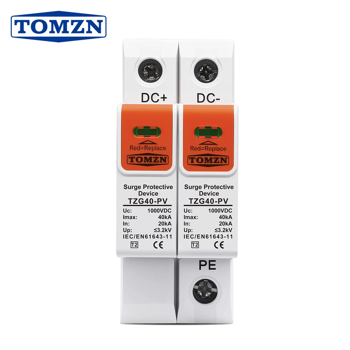
For a 1000V nominal DC solar system, you should select a dc spd with a maximum continuous operating voltage of at least 1000V DC, and ideally with a rated voltage that accounts for the maximum open-circuit voltage of your string under cold-temperature conditions. Many installers choose a dc spd rated at 1000V or 1200V to ensure adequate margin. Always verify the actual Voc of your array at the lowest expected ambient temperature before finalizing the selection.
Can I use the same dc spd for both the combiner box and the inverter input?
Yes, in many cases the same model of dc spd can be used at both locations, provided the voltage and current ratings are appropriate for both positions in the circuit. However, the device at the combiner box may be exposed to higher surge currents due to its proximity to the array, so some designers choose a higher Imax rating for that position. The inverter-side dc spd can often be a standard 20kA device, while the combiner box position may warrant a 40kA unit in high-risk environments.
How do I know when my dc spd needs to be replaced?
Most dc spd devices include a visual status indicator that changes appearance when the device has reached end of life or has been thermally disconnected after absorbing a large surge. Check the indicator window during every maintenance visit. A change from the normal 'healthy' color or position to the 'fault' indication means the device should be replaced promptly. If your system includes remote monitoring with auxiliary contacts, you may receive an automated alert before the next scheduled visit.
Is a dc spd required by electrical codes for solar installations?
Requirements vary by jurisdiction and installation type, but many national and regional electrical codes — including standards aligned with IEC 60364 and NEC Article 690 — either require or strongly recommend surge protection on the DC side of solar photovoltaic systems, particularly for systems above certain voltage or power thresholds. Beyond code compliance, the practical case for installing a dc spd is compelling on its own merits: the cost of the device is a small fraction of the equipment it protects, and the risk of surge damage in outdoor solar environments is well documented.