
In power systems engineering, the difference between a smooth transition and a catastrophic equipment failure often comes down to milliseconds. When utility power unexpectedly fails, an ats — or automatic transfer switch — becomes the first and most critical line of defense. Its job is to sense the power loss and switch the load to an alternate source as quickly and reliably as possible, and the speed at which it does this is far more consequential than many facility managers and engineers initially realize.
The significance of ats switching speed is not simply about convenience or avoiding minor disruptions. In critical power environments — including hospitals, data centers, industrial plants, telecommunications hubs, and emergency response facilities — an ats that transfers too slowly can lead to data corruption, equipment damage, process shutdowns, and even life-threatening situations. Understanding why switching speed matters, how it is measured, and what influences it is essential knowledge for anyone responsible for power system reliability and continuity.
The Role of an ATS in Power Continuity
What an ATS Actually Does in a Fault Scenario
An ats continuously monitors the incoming utility power supply for voltage sags, frequency deviations, or complete outages. The moment a fault is detected that falls outside pre-set acceptable thresholds, the ats initiates a transfer sequence. This sequence disconnects the load from the primary source and reconnects it to a standby or backup source — such as a diesel generator, UPS output, or second utility feed — with minimal interruption to the connected equipment.
The ats performs this function autonomously, without requiring human intervention. This autonomy is precisely why its internal timing logic must be calibrated carefully. A well-configured ats does not simply react; it evaluates the severity of the power event, determines whether the disturbance is transient or sustained, and then executes the transfer at the right moment. Every fraction of a second in that decision window carries operational consequences.
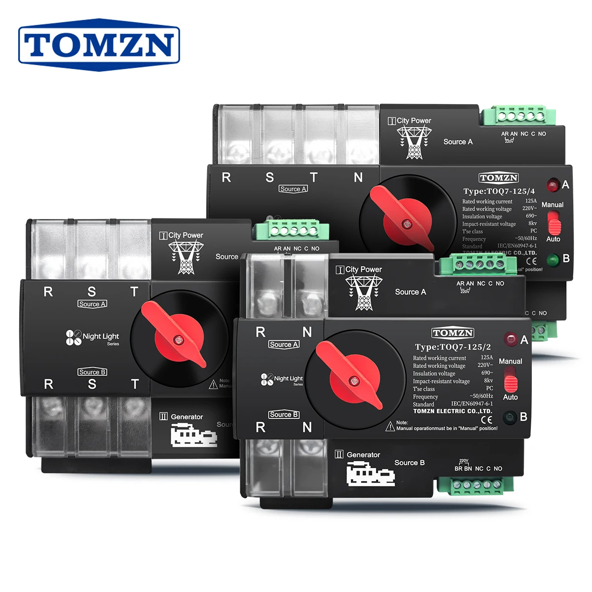
Modern ats units designed for DIN rail mounting and three-phase configurations offer dual-power automatic transfer capability that allows seamless switching between two independent power inputs. This makes them particularly valuable in environments where even brief interruptions are unacceptable and redundancy must be built into the distribution architecture from the panel level upward.
Why Switching Speed Is a Performance Parameter, Not a Feature
Many engineers mistakenly treat ats switching speed as a secondary specification, focusing instead on current rating, voltage range, or number of poles. In reality, switching speed is a primary performance parameter that determines whether the ats can fulfill its fundamental purpose. A switch that takes three to five seconds to transfer may technically work, but for many critical applications that delay represents an unacceptably long interruption.
The switching speed of an ats is typically expressed in cycles or milliseconds and includes several sub-intervals: the sensing time, the decision delay, the mechanical or electronic actuation time, and the stabilization period before loads reconnect. Each of these intervals contributes to the total transfer time, and each can be a source of variability if the ats is not properly designed or maintained.
For applications where the ats feeds sensitive electronic equipment, variable-frequency drives, or programmable logic controllers, the acceptable window of power interruption may be as narrow as 10 to 20 milliseconds. This places significant engineering demands on the ats and its supporting control circuitry, making the switching speed specification one of the most critical criteria in the selection process.
Critical Power Applications Where ATS Speed Is Non-Negotiable
Healthcare and Life-Safety Environments
In healthcare facilities, the ats is a regulatory and safety-critical component. Operating theaters, intensive care units, and emergency departments rely on continuous power for ventilators, infusion pumps, patient monitoring systems, and surgical lighting. Any power interruption lasting longer than a fraction of a second can disrupt equipment that lacks internal energy storage, potentially compromising patient safety during a procedure.
Healthcare electrical standards in many jurisdictions require that the ats complete the transfer to emergency power within a specific time limit — often no more than 10 seconds for life-safety circuits and as fast as possible for critical care areas. Meeting these standards is not optional; failure to comply can result in facility accreditation issues. But beyond regulatory compliance, the ethical imperative is clear: an ats in a hospital must transfer quickly enough that clinical operations are never interrupted at a critical moment.
The ats units used in healthcare settings typically incorporate redundant sensing circuits, fail-safe mechanical designs, and self-testing routines to ensure that the switching speed remains consistent over years of standby operation. This reliability over time is just as important as the rated switching speed itself.
Data Centers and IT Infrastructure
Data centers represent one of the most demanding environments for ats performance. Servers, storage arrays, and networking equipment are highly sensitive to power quality events. Even a momentary interruption lasting longer than the hold-up time of internal power supplies — typically 10 to 20 milliseconds — can cause server crashes, file system corruption, or unexpected reboots that take time to recover from and may result in data loss.
In a properly designed data center power architecture, the ats works in conjunction with uninterruptible power supplies and generator systems to create a layered resilience strategy. The ats must transfer fast enough that the UPS batteries do not discharge significantly before the generator comes online. If the ats is slow, the UPS must compensate for a longer bridge period, increasing battery wear and reducing system-level reliability over time.
For high-density computing environments, the ats is often installed at the panel or distribution board level, using DIN rail-mounted units rated for the specific phase configuration and current draw of the equipment it protects. The ability of the ats to handle three-phase loads while maintaining fast, balanced transfer across all phases simultaneously is essential to avoiding phase imbalance events during the switching sequence.
Industrial Automation and Process Control
In manufacturing and process industries, the ats protects programmable controllers, motion drives, sensor networks, and safety instrumented systems. Many industrial processes cannot tolerate even a brief power interruption without triggering automated safety shutdowns, which can take hours to recover from and may result in significant production losses or material waste.
Consider a continuous casting line in a steel plant, a pharmaceutical cleanroom environment, or a precision injection molding operation. In each case, an ats that transfers too slowly allows the process to fall outside its controlled operating window, forcing an unplanned stop. The cost of that stop — in lost materials, labor, equipment recalibration, and restart time — can far exceed the cost of upgrading to a faster, higher-specification ats unit.
Industrial ats applications also demand robust mechanical design that can withstand vibration, temperature cycling, and the electromagnetic noise characteristic of motor-heavy environments. The ats must maintain its rated switching speed under all operating conditions, not just under ideal laboratory conditions.
How Switching Speed Is Determined and Measured
The Anatomy of an ATS Transfer Sequence
Understanding total ats transfer time requires breaking the switching event into its constituent phases. The first phase is the detection window — the time from when the power fault occurs to when the ats control circuit confirms that the event is real and not a transient. This window is typically set intentionally to avoid nuisance transfers caused by brief voltage sags that self-correct within a few cycles.
The second phase is the actuation time — how long it takes the mechanical contacts or electronic switching elements within the ats to physically change position and complete the circuit to the alternate source. Electromechanical ats designs rely on solenoid coils and spring-loaded contacts, while static ats designs use thyristors or solid-state relays that can switch in sub-cycle timeframes. The technology choice here fundamentally shapes the minimum achievable switching speed.
The third phase involves source confirmation — verifying that the alternate source is stable and within acceptable voltage and frequency limits before completing the transfer. A well-designed ats incorporates this confirmation step to prevent transferring loads onto a generator that has not yet reached stable output, which could cause secondary damage to sensitive equipment. The total of these three phases defines the actual transfer time that system designers must account for.
Static Versus Electromechanical ATS Designs
The design architecture of an ats has a direct and significant impact on its achievable switching speed. Electromechanical ats units use motorized or solenoid-driven contacts and are capable of transfer times in the range of 20 to 100 milliseconds under optimized conditions. For many general commercial and light industrial applications, this range is perfectly adequate and offers the advantages of low on-state losses and established reliability.
Static ats units, which use solid-state switching elements, can achieve transfer times well below one cycle — in some designs as fast as two to four milliseconds. This near-instantaneous transfer is valuable for the most sensitive loads but comes with higher costs and the need for careful thermal management of the power electronics. The choice between static and electromechanical ats technology depends on the specific sensitivity profile of the connected loads.
For many DIN rail-mounted ats units used in commercial buildings and medium-scale industrial panels, the electromechanical design with a rated switching speed of 20 milliseconds or less provides an excellent balance between speed, cost, and long-term reliability. When evaluating an ats for a specific application, it is important to review the manufacturer's specification for both the typical and worst-case transfer times, as these can differ meaningfully under varying load and ambient conditions.
Factors That Influence Real-World ATS Switching Performance
Load Type and Sensitivity Profile
The switching speed requirement for an ats is not a fixed universal value — it is determined by the specific characteristics of the loads it protects. Resistive loads such as lighting or heating elements are generally tolerant of brief interruptions, and an ats with a moderate switching speed is perfectly suitable. Inductive loads like motors may experience speed dip or torque pulsation during a transfer but typically recover quickly if the ats completes the sequence within a few cycles.
Electronic loads with switched-mode power supplies are the most demanding. The hold-up capacitors within a typical server power supply provide ride-through capability for 10 to 20 milliseconds. If the ats transfer time exceeds this window, the power supply output collapses and the server shuts down. Selecting an ats with a switching speed that comfortably fits within the load's hold-up time is the fundamental engineering requirement for protecting electronic infrastructure.
Mixed-load panels — which combine motors, electronic equipment, and lighting on the same distribution circuit — require the ats to be rated to the fastest-responding load in the group. Designing the ats selection around the most sensitive load type is conservative practice that protects the entire panel from the consequences of a slow transfer.
Environmental and Maintenance Factors
Even a high-specification ats can deliver slower-than-rated switching times if it is not properly installed and maintained. Contact wear in electromechanical ats units can cause increased actuation time as the mechanism ages. Accumulated dust or moisture can slow mechanical movement or create partial contact resistance that delays the switching sequence. Regular inspection and testing of the ats — including exercise cycles under load — helps confirm that the switching speed remains within specification over time.
Ambient temperature also affects ats performance. High temperatures increase the resistance of control circuit components and can slow the response of solenoid coils. Installing the ats in a properly ventilated enclosure and respecting the manufacturer's temperature derating guidelines ensures that the switching speed performance degrades predictably rather than unexpectedly.
Voltage levels at the control circuit terminals also matter. An ats with a marginal control supply voltage may take longer to actuate than one operating at the nominal rated voltage. Ensuring stable control power — often derived from the same or a separate reliable source — is a detail that has real impact on the consistency of ats switching performance in the field.
Selecting the Right ATS Switching Speed for Your Application
Matching ATS Specifications to System Requirements
Selecting the correct ats begins with a clear understanding of the most sensitive load's power interruption tolerance. Once this is established, the required transfer time can be calculated by subtracting a safety margin from the load's hold-up time. This target transfer time then becomes the primary specification that filters the available ats options.
For three-phase systems operating at 230V per phase, a DIN rail-mounted ats rated at 63A, 100A, or 125A with dual-power automatic transfer capability provides a compact and highly practical solution for protecting critical panel sections. These units combine the ats sensing, switching, and source selection functions in a single device that integrates cleanly into standard distribution panels without requiring dedicated control panels or complex wiring schemes.
Beyond the switching speed itself, the ats specification review should include the detection threshold settings — the voltage and frequency deviation levels that trigger a transfer — as well as the adjustability of these thresholds. An ats that can be fine-tuned to match the specific voltage tolerance window of the connected loads offers significantly more operational value than one with fixed, non-adjustable detection settings.
Practical Commissioning and Verification Steps
Once an ats is selected and installed, verifying its actual switching speed under operational conditions is an essential commissioning step. This is typically done by simulating a power fault on the primary source while monitoring the transfer event with an oscilloscope or power quality analyzer. The measured transfer time should be compared against the manufacturer's specification to confirm that the installation is performing as designed.
Periodic retesting of the ats — at least annually for critical applications — ensures that switching speed degradation is detected before it causes an operational problem. Many modern ats units incorporate built-in test functions that allow the switching sequence to be exercised without fully interrupting power to the load, making routine verification straightforward and minimally disruptive.
Documenting the ats commissioning results and subsequent test records also serves a compliance function in regulated industries, providing evidence that the power protection system is functioning within its specified parameters and that the ats is ready to perform its role when a real power fault occurs.
FAQ
What is a typical acceptable switching speed for an ATS in a data center?
For data center applications, an ats with a total transfer time of 10 milliseconds or less is generally preferred to ensure that server power supplies do not drop below their hold-up threshold during the transition. Some high-availability environments specify even faster transfer times and may use static ats technology to achieve sub-cycle switching.
Can an ATS transfer too quickly and cause problems?
In some cases, an ats that transfers before confirming that the alternate source is stable can cause secondary issues. A very fast ats must still include source quality verification to ensure the backup supply is within acceptable voltage and frequency limits before completing the transfer. Most well-designed ats units incorporate this protection to prevent transferring loads onto an unstable source.
How does a three-phase ATS maintain switching speed balance across phases?
A three-phase ats is designed to switch all three phases simultaneously, ensuring that no phase imbalance occurs during the transfer event. The mechanical or electronic actuation of all poles is synchronized within the ats design so that the transfer completes in a coordinated manner. Reviewing the phase synchronization specification is important when evaluating an ats for three-phase sensitive loads.
How often should the ATS switching speed be tested in a critical facility?
For most critical facilities, annual testing of the ats switching speed under load conditions is the minimum recommended practice. High-criticality environments such as hospitals, data centers, and emergency control rooms may require quarterly or even monthly test cycles to ensure consistent performance. Many current ats models include self-test functionality that simplifies this routine without requiring manual simulation of power faults.